Языки: Венгерский , Греческий , Испанский , Итальянский , Немецкий , Польский , Португальский , Русский , Турецкий , Французский , Чешский
Тип: PDF
Размер: 18.6 MB
Описание: Installation Guidebook
Языки: Английский , Русский
Тип: PDF
Размер: 18.18 MB
Описание: Материнская плата
Языки: Русский
Тип: PDF
Размер: 14.67 MB
Описание: Материнская плата
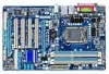
На NoDevice можно скачать инструкцию по эксплуатации для Gigabyte GA-P55-UD3L. Руководство пользователя необходимо для ознакомления с правилами установки и эксплуатации Gigabyte GA-P55-UD3L. Инструкции по использованию помогут правильно настроить Gigabyte GA-P55-UD3L, исправить ошибки и выявить неполадки.
Для просмотра содержания инструкции Вам понадобится программа Adobe Reader или DjVu.
Если на Вашем компьютере они не установлены, то Adobe Reader можно скачать с сайта Adobe , а DjVu с сайта DjVu
Смотрите также другие инструкции раздела Материнские платы:
Gigabyte GA-P55-UD3L | Manual — Page 4 with the product. For detailed product information, carefully read the User’s Manual. For instructions on how to use GIGABYTE’s unique features, read or download the information on/from the Support&DownloadsMotherboardTechnology Guide page on our
Gigabyte GA-P55-UD3L | Manual — Page 7 Box Contents GA-P55-UD3L-TPM, GA-P55-UD3L, or GA-P55-US3L motherboard Motherboard driver disk User’s Manual Quick Installation Guide One IDE cable Two SATA 3Gb/s cables I/O Shield • The box contents above are for reference only and the actual items shall
Gigabyte GA-P55-UD3L | Manual — Page 9 PCI Express Bus DMI Interface 1 PCI Express x4 x4 PCI Express Bus Intel® P55 PCIe CLK (100 MHz) 1 PCI Express x1 Dual BIOS 6 SATA 3Gb/s 2 Speaker Out) Line-Out (Front Speaker Out) Line-In (Rear Speaker Out) TPM j S/PDIF In S/PDIF Out j Only for GA-P55-UD3L-TPM. 4 PCI PCI CLK (33 MHz) -9-
Gigabyte GA-P55-UD3L | Manual — Page 10 — 10 —
Gigabyte GA-P55-UD3L | Manual — Page 11 discharge (ESD). Prior to installation, carefully read the user’s manual and follow these procedures: wrist strap when handling electronic components such as a motherboard, CPU or memory. If you do harm to the user. • If you are uncertain about any installation steps or have a problem related
Gigabyte GA-P55-UD3L | Manual — Page 12 latest CPU support list.) L3 cache varies with CPU Intel® P55 Express Chipset Chipset Memory Audio LAN to 1 floppy disk drive Expansion Slots Multi-Graphics Technology Storage Interface «*» The GA-P55-UD3L-TPM/GA-P55-UD3L adopts All-Solid Capacitor design
Gigabyte GA-P55-UD3L | Manual — Page 13 CPU/System/Power fan fail warning CPU/System fan speed control (Note 5) 2 x 16 Mbit flash Use of licensed AWARD BIOS Support for DualBIOS™ PnP 1.0a, DMI 2.0, SM BIOS 2.4, ACPI 1.0b I/O Controller Hardware Monitor BIOS — 13 — Hardware Installation
Gigabyte GA-P55-UD3L | Manual — Page 14 Security (OEM version) Support for Microsoft® Windows® 7/Vista/XP ATX Form Factor; 30.5cm x 19.0cm j Only for GA-P55-UD3L-TPM. (Note 1) Due to Windows Vista/XP 32-bit operating system limitation, when more than 4 GB of physical memory is
Gigabyte GA-P55-UD3L | Manual — Page 15 CPU Cooler Read the following guidelines before you begin to install the CPU: • Make sure that the motherboard supports the CPU. (Go to GIGABYTE’s website for the latest CPU support list.) • Always turn off the computer and unplug the power cord from
Gigabyte GA-P55-UD3L | Manual — Page 16 Follow the steps below to correctly install the CPU into the motherboard CPU socket. Before installing (DO NOT touch socket contacts. To protect the CPU socket, always replace the protective socket position. Hardware Installation — 16 — NOTE: Hold the CPU socket lever by the handle, not the lever
Gigabyte GA-P55-UD3L | Manual — Page 17 Check that the Male and Female push pins are joined closely. (Refer to your CPU cooler installation manual for instructions on installing the cooler.) Step 5: After the installation, check the back of the motherboard. If the push pin is inserted as the
Gigabyte GA-P55-UD3L | Manual — Page 18 of the same capacity, brand, speed, and chips be used. (Go to GIGABYTE’s website for the latest memory support list.) • Always turn off the computer memory, switch the direction. 1-4-1 Dual Channel Memory Configuration This motherboard provides four DDR3 memory sockets and supports
Gigabyte GA-P55-UD3L | Manual — Page 19 outlet to prevent damage to the memory module. DDR3 and DDR2 DIMMs are not compatible to each other or DDR DIMMs. Be sure to install DDR3 DIMMs on this motherboard. Notch DDR3 DIMM A DDR3 memory module has a notch, so it can only fit in one direction. Follow the steps below to correctly install
Gigabyte GA-P55-UD3L | Manual — Page 20 an expansion card: • Make sure the motherboard supports the expansion card. Carefully read the manual that came with your expansion card. • Always turn off the the chassis cover(s). 6. Turn on your computer. If necessary, go to BIOS Setup to make any required BIOS changes
Gigabyte GA-P55-UD3L | Manual — Page 21 1-6 Back Panel Connectors USB Port The USB port supports the USB 2.0/1.1 specification. Use this port for USB devices such as a USB keyboard/mouse, USB printer, provides digital audio out to an external audio system that supports digital coaxial audio. Before using this feature
Gigabyte GA-P55-UD3L | Manual — Page 22 the port of HD Audio standard via front panel and enable the multi-channel audio feature through the audio driver. Refer to the instructions on setting up a 2/4/5.1/7.1-channel audio configuration in Chapter 5, «Configuring 2/4/5.1/7.1-Channel
Gigabyte GA-P55-UD3L | Manual — Page 23 off the devices and your computer. Unplug the power cord from the power outlet to prevent damage to the devices. • After installing the device and before turning on the computer, make sure the device cable has been securely attached to the connector on the motherboard. — 23 Hardware Installation
Gigabyte GA-P55-UD3L | Manual — Page 24 power supply can supply enough stable power to all the components on the motherboard. Before connecting the power connector, first make sure the power supply, remove the protective cover from the main power connector on the motherboard. Do not insert the power supply cable into pins
Gigabyte GA-P55-UD3L | Manual — Page 25 3/4/5) CPU_FAN/SYS_FAN1/SYS_FAN2/PWR_FAN (Fan Headers) The motherboard has a 4-pin CPU fan header (CPU_FAN), a 4-pin (SYS_FAN2) to connect it in the correct orientation (the black connector wire is the ground wire). The motherboard supports CPU fan speed control, which requires the use of a CPU fan
Gigabyte GA-P55-UD3L | Manual — Page 26 master/slave settings for the IDE devices, read the instructions from the device manufacturers.) 39 1 40 2 8) SATA2_0/1/2/3/4/5 (SATA 3Gb/s Connectors, Controlled by P55 Chipset) The SATA connectors conform to SATA 3Gb/s standard and are
Gigabyte GA-P55-UD3L | Manual — Page 27 9) GSATA2_0/1 (SATA 3Gb/s Connectors, Controlled by GIGABYTE SATA2) The SATA connectors conform to SATA 3Gb/s standard and . Each SATA connector supports a single SATA device. The GIGABYTE SATA2 controller supports RAID 0, RAID 1, and JBOD. Refer to Chapter 5, «Configuring SATA Hard Drive(s),» for
Gigabyte GA-P55-UD3L | Manual — Page 28 is detected at system startup. If a problem is detected, the BIOS may issue beeps in different patterns to indicate the problem. Refer to Chapter 5, «Troubleshooting,» for information about beep codes. • HD (Hard Drive Activity LED, Blue) Connects to
Gigabyte GA-P55-UD3L | Manual — Page 29 of the module connector match the pin assignments of the motherboard header. Incorrect connection between the module connector and the motherboard header will make the device unable to work or even damage it. 2 1 10 9 to mute the back panel audio (only supported when using an HD front panel audio
Gigabyte GA-P55-UD3L | Manual — Page 30 by expansion cards) for digital audio output from your motherboard to certain expansion cards like graphics cards audio cable for digital audio output from your motherboard to your graphics card if you wish S/PDIF digital audio cable, carefully read the manual for your expansion card. 1 Pin No.
Gigabyte GA-P55-UD3L | Manual — Page 31 (USB Headers) The headers conform to USB 2.0/1.1 specification. Each USB header can provide two USB so may cause damage to the motherboard. • After system restart, go to BIOS Setup to load factory defaults (select Load Optimized Defaults) or manually configure the BIOS settings (refer to Chapter
Gigabyte GA-P55-UD3L | Manual — Page 32 18) PHASE LED The number of lighted LEDs indicates the CPU loading. The higher the CPU loading, the more the number of lighted LEDs. To enable the Phase LED display function, please first enable Dynamic Energy Saver™ 2. Refer to Chapter 4, «Dynamic Energy Saver™ 2,» for more details. Hardware
Gigabyte GA-P55-UD3L | Manual — Page 33 BIOS Setup program. To upgrade the BIOS, use either the GIGABYTE Q-Flash or @BIOS utility. • Q-Flash .» • Because BIOS flashing is potentially risky, if you do not encounter problems malfunction. • BIOS will emit a beep code during the POST. Refer to Chapter 5, «Troubleshooting,» for the beep
Gigabyte GA-P55-UD3L | Manual — Page 34 Award Modular BIOS v6.00PG, An Energy Star Ally Copyright (C) 1984-2009, Award Software, Inc. P55-UD3L D11 . BIOS Setup : XpressRecovery2 : Boot Menu : Qflash 07/17/2009-P55-7A89RG0LC-00 Motherboard Model BIOS Version Function Keys Function Keys: >>>> Advanced Clock Control CPU Clock Drive PCI Express Clock item is present only if you install a CPU that supports this feature. For more information about Intel CPUs appears only if you install a memory module that supports this feature. — 37 BIOS Setup
Gigabyte GA-P55-UD3L | Manual — Page 38 (C1E) (Note) C3/C6/C7 State Support (Note) CPU Thermal Monitor (Note) CPU to enable multi-threading technology when using an Intel CPU that supports this function. This feature only works for item is present only if you install a CPU that supports this feature. For more information about Intel CPUs
Gigabyte GA-P55-UD3L | Manual — Page 39 C3/C6/C7 State Support (Note) Allows you to determine whether to let the CPU enter C3/C6/C7 mode in system halt Ratio Uncore Frequency (Note) This item is present only if you install a CPU that supports this feature. For more information about Intel CPUs’ unique features, please visit Intel
Gigabyte GA-P55-UD3L | Manual — Page 40 only if the Base Clock(BCLK) Control option is enabled. Important: It is highly recommended that the CPU frequency be set in accordance with the CPU specifications. Allows the BIOS when enabled. Disabled Profile1 Profile2 (Note) to read the SPD data on XMP
Gigabyte GA-P55-UD3L | Manual — Page 41 >>>>> Advanced Clock Control CPU Clock Drive Allows you to adjust the amplitude of the CPU and Chipset clock. Options are: 700mV (default), Frequency(Mhz) and System Memory Multiplier settings. This item appears only if you install a memory module that supports this feature. — 41 BIOS Setup (Note)
Gigabyte GA-P55-UD3L | Manual — Page 42 Channel A Timing Settings x x x x x x x x x x x x x x x x >>>>> Channel A Standard Timing Control CAS Latency Time 7 tRCD 7 tRP 7 tRAS 20 >>>>> Channel A Advanced Timing Control tRC 28 tRRD 4 tWTR 5 tWR Fail-Safe Defaults >>>>> Channel A/B Standard Timing Control CAS Latency Time tRCD Options
Gigabyte GA-P55-UD3L | Manual — Page 43 Auto (default), 1
31. >>>>> Channel A/B Advanced Timing Control tRC tRRD Options are: Auto (default), Options are: Auto (default), 1
3. >>>>> Channel A/B Misc Timing Control tWTR tWR tWTP tWL tRFC Latency Options are: Auto (default), 1



 , а DjVu с сайта DjVu