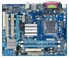
Если у вас отсутствует техническая возможность для скачивания Руководство по эксплуатации для GIGABYTE GA-G41M-ES2L (rev. 1.1) вы можете прочесть документ прямо на нашем сайте или Скачать GIGABYTE GA-G41M-ES2L (rev. 1.1) Руководство по эксплуатации
Языки: Венгерский , Греческий , Испанский , Итальянский , Немецкий , Польский , Португальский , Русский , Турецкий , Французский , Чешский
Тип: PDF
Размер: 18.6 MB
Описание: Installation Guidebook
На NoDevice можно скачать инструкцию по эксплуатации для Gigabyte GA-G41M-ES2L. Руководство пользователя необходимо для ознакомления с правилами установки и эксплуатации Gigabyte GA-G41M-ES2L. Инструкции по использованию помогут правильно настроить Gigabyte GA-G41M-ES2L, исправить ошибки и выявить неполадки.
Gigabyte GA-G41M-ES2L | Manual — Page 2 Motherboard GA-G41M-ES2L Motherboard GA-G41M-ES2L Mar. 27, 2009 Mar. 27, 2009
Gigabyte GA-G41M-ES2L | Manual — Page 3 For detailed product information, carefully read the User’s Manual. For instructions on how to use GIGABYTE’s unique features, read or download the information on/from the SupportMotherboardTechnology Guide page on our website. For product-related
Gigabyte GA-G41M-ES2L | Manual — Page 5 . 57 Applications Software . 58 Technical Manuals . 58 Contact . 59 System . 59 60 Chapter 4 Unique Features . 61 4-1 4-2 Xpress Recovery2 . 61 BIOS Update Utilities . 64 with the Q-Flash Utility . 64 Updating the BIOS with the @BIOS Utility . 67 4-3 4-4 4-5 4-6 EasyTune 6 . 68 Easy
Gigabyte GA-G41M-ES2L | Manual — Page 6 Box Contents GA-G41M-ES2L motherboard Motherboard driver disk User’s Manual One IDE cable Two SATA 3Gb/s cables I/O Shield • The box contents above are for reference only and the actual items shall depend on the product package you obtain. The box contents are subject to change
Gigabyte GA-G41M-ES2L | Manual — Page 7 GA-G41M-ES2L Motherboard Layout KB_MS ATX_12V CPU_FAN COMA LGA775 VGA LPT ATX R_USB AUDIO F_AUDIO Intel® G41 GA-G41M-ES2L IDE USB LAN COMB RTL8111C/D(L) PCIEX16 CLR_CMOS BATTERY B_BIOS M_BIOS IT8718 PCI1 SPDIF_IO CODEC PCI2 SYS_FAN FDD Intel ® ICH7 CI PWR_LED DDR2_2
Gigabyte GA-G41M-ES2L | Manual — Page 9 Chapter 1 Hardware Installation 1-1 Installation Precautions The motherboard contains numerous delicate electronic circuits and components which (ESD) wrist strap when handling electronic components such as a motherboard, CPU or memory. If you do not have an ESD wrist strap, keep your hands dry
Gigabyte GA-G41M-ES2L | Manual — Page 10 ® Celeron® processor in the LGA 775 package (Go to GIGABYTE’s website for the latest CPU support list.) L2 cache varies with CPU 1333/1066/800 MHz TM TM Front Side Bus Chipset Memory Onboard Graphics Audio LAN Expansion Slots Storage Interface USB GA-G41M-ES2L Motherboard — 10 —
Gigabyte GA-G41M-ES2L | Manual — Page 11 fan speed detection CPU overheating warning CPU/System fan fail warning CPU fan speed control (Note 3) 2 x 8 Mbit flash Use of licensed AWARD BIOS Support for DualBIOSTM PnP 1.0a, DMI 2.0, SM BIOS 2.4, ACPI 1.0b — 11 — Hardware Installation
Gigabyte GA-G41M-ES2L | Manual — Page 12 and enable the multi-channel audio feature through the audio driver. (Note 3) Whether the CPU fan speed control function is supported will depend on the CPU you install Core/ Celeron Dual-Core/ Celeron 400 Series CPU to enable support for Easy Energy Saver. TM TM TM GA-G41M-ES2L Motherboard — 12 —
Gigabyte GA-G41M-ES2L | Manual — Page 13 before you begin to install the CPU: • Make sure that the motherboard supports the CPU. (Go to GIGABYTE’s website for the latest CPU support list.) • Always turn off the computer and unplug the power cord from the power outlet before installing
Gigabyte GA-G41M-ES2L | Manual — Page 14 keys) and gently insert the CPU into position. Step 5: Once the CPU is properly inserted, replace the load plate and push the CPU socket lever back into its locked position. GA-G41M-ES2L Motherboard — 14 —
Gigabyte GA-G41M-ES2L | Manual — Page 15 pins are joined closely. (Refer to your CPU cooler installation manual for instructions on installing the cooler.) Step 5: After the installation, check the back of the motherboard. If the push pin is inserted as the picture above, the
Gigabyte GA-G41M-ES2L | Manual — Page 16 capacity, brand, speed, and chips be used. (Go to GIGABYTE’s website for the latest memory support list.) • Always turn off the computer and mode with two memory modules, it is recommended that memory of the same capacity, brand, speed, and chips be used. GA-G41M-ES2L Motherboard — 16 — DDR2_2
Gigabyte GA-G41M-ES2L | Manual — Page 17 DDR DIMMs. Be sure to install DDR2 DIMMs on this motherboard. Notch DDR2 DIMM A DDR2 memory correctly install your memory modules in the memory sockets. Step 1: Note the orientation of the memory module on the memory and insert it vertically into the memory socket. Step 2: The clips at both ends
Gigabyte GA-G41M-ES2L | Manual — Page 18 the card is securely seated in the slot and does not rock. • Removing the Card: Gently push back on the lever on the slot and then lift the card straight out from the slot. GA-G41M-ES2L Motherboard — 18 —
Gigabyte GA-G41M-ES2L | Manual — Page 19 peripherals. D-Sub Port The D-Sub port supports a 15-pin D-Sub connector. Connect to this port. USB 2.0/1.1 Port The USB port supports the USB 2.0/1.1 specification. Use this port for USB from your device and then remove it from the motherboard. • When removing the cable, pull it straight out
Gigabyte GA-G41M-ES2L | Manual — Page 20 multi-channel audio feature through the audio driver. Refer to the instructions on setting up a 2/4/5.1/7.1-channel audio configuration in Chapter 5, «Configuring 2/4/5.1/7.1-Channel Audio.» GA-G41M-ES2L Motherboard — 20 —
Gigabyte GA-G41M-ES2L | Manual — Page 21 off the devices and your computer. Unplug the power cord from the power outlet to prevent damage to the devices. • After installing the device and before turning on the computer, make sure the device cable has been securely attached to the connector on the motherboard. — 21 Hardware Installation
Gigabyte GA-G41M-ES2L | Manual — Page 22 power connector, the power supply can supply enough stable power to all the components on the motherboard. Before connecting the power connector, first make sure the power supply is turned 5V +5V +5V +5V (Only for 2×12-pin ATX) GND (Only for 2×12-pin ATX) 1 13 ATX GA-G41M-ES2L Motherboard — 22 —
Gigabyte GA-G41M-ES2L | Manual — Page 23 3/4) CPU_FAN/SYS_FAN (Fan Headers) The motherboard has a 4-pin CPU fan header (CPU_FAN) and a 3-pin ( When connecting a fan cable, be sure to connect it in the correct orientation (the black connector wire is the ground wire). The motherboard supports CPU fan speed control, which requires the use of
Gigabyte GA-G41M-ES2L | Manual — Page 24 to SATA 3Gb/s standard and are compatible with SATA 1.5Gb/s standard. Each SATA connector supports a single SATA device. Pin No. 1 7 SATA2_3 7 SATA2_2 7 7 SATA2_0 1 RXP GND 2 3 4 5 6 7 Please connect the L-shaped end of the SATA 3Gb/s cable to your SATA hard drive. GA-G41M-ES2L Motherboard — 24 —
Gigabyte GA-G41M-ES2L | Manual — Page 25 2 1 Definition MPD+ MPDMPD- 3 System Status LED S0 S1 S3/S4/S5 On Blinking Off 9) BATTERY The battery provides power to keep the values (such as BIOS configurations, date, and time information) in the CMOS when the computer is turned off. Replace the battery when the battery voltage drops to a
Gigabyte GA-G41M-ES2L | Manual — Page 26 hard drive activity LED, speaker and etc. When connecting your chassis front panel module to this header, make sure the wire assignments and the pin assignments are matched correctly. GA-G41M-ES2L Motherboard — 26 —
Gigabyte GA-G41M-ES2L | Manual — Page 27 11) F_AUDIO (Front Panel Audio Header) The front panel audio header supports Intel of the module connector match the pin assignments of the motherboard header. Incorrect connection between the module and the motherboard header will make the device unable to work or even damage it. 2 1 For HD Front
Gigabyte GA-G41M-ES2L | Manual — Page 28 the USB header. • Prior to installing the USB bracket, be sure to turn off your computer and unplug the power cord from the power outlet to prevent damage to the USB bracket. GA-G41M-ES2L Motherboard — 28 —
Gigabyte GA-G41M-ES2L | Manual — Page 29 the jumper cap from the jumper. Failure to do so may cause damage to the motherboard. • After system restart, go to BIOS Setup to load factory defaults (select Load Optimized Defaults) or manually configure the BIOS settings (refer to Chapter 2, «BIOS Setup,» for BIOS
Gigabyte GA-G41M-ES2L | Manual — Page 30 17) CI (Chassis Intrusion Header) This motherboard provides a chassis detection feature that detects if the chassis cover has been removed. This function requires a chassis with chassis intrusion detection design. Pin No. 1 1 Definition Signal GND 2 GA-G41M-ES2L Motherboard — 30 —
Gigabyte GA-G41M-ES2L | Manual — Page 31 BIOS Setup program. To upgrade the BIOS, use either the GIGABYTE Q-Flash or @BIOS utility. • Q-Flash utilities, refer to Chapter 4, «BIOS Update Utilities.» • Because BIOS flashing is potentially risky, flashing may result in system malfunction. • BIOS will emit a beep code during the POST.
Gigabyte GA-G41M-ES2L | Manual — Page 32 -2009, Award Software, Inc. The following screens may appear when the computer boots. Motherboard Model BIOS Version G41MES2L F5F EuP . BIOS Setup : Press the key to access the Q-Flash utility directly without having to enter BIOS Setup first. GA-G41M-ES2L Motherboard — 32 —
Gigabyte GA-G41M-ES2L | Manual — Page 33 or enter the submenu Main Menu: Exit the BIOS Setup program Submenus: Exit current settings for the current submenus Load the Optimized BIOS default settings for the current submenus Access item to set your system to its defaults. • The BIOS Setup menus described in this chapter are for reference
Gigabyte GA-G41M-ES2L | Manual — Page 34 , floppy disk drive types, and the type of errors that stop the system boot, etc. Advanced BIOS Features Use this menu to configure the device boot order Pressing to the confirmation message will exit BIOS Setup. (Pressing can also carry out this task.) GA-G41M-ES2L Motherboard — 34 —
Gigabyte GA-G41M-ES2L | Manual — Page 35 is dependent on your overall system configurations. Incorrectly doing overclock/overvoltage may result in damage to CPU, chipset, or memory and reduce the useful life reset the board to default values.) (Note) This item appears only if you install a CPU that supports this feature. — 35 BIOS Setup
Gigabyte GA-G41M-ES2L | Manual — Page 36 Frequency Latch settings. Auto sets memory multiplier according to memory SPD data. (Default: Auto) (Note) This item appears only if you install a CPU that supports this feature. GA-G41M-ES2L Motherboard — 36 —
Gigabyte GA-G41M-ES2L | Manual — Page 37 second is the memory frequency that is automatically adjusted according to the CPU Host Frequency (Mhz) and System Multiplier settings. DRAM Timing Selectable (SPD) Manual allows all DRAM timing control Options are: Auto (default), 1